Back
Behind the Scenes: How the Digital Twin Approach Empowered the Fabrication/Construction Process of the Complex PDX Mass Timber Roof
May 5, 2022
| 4 minute read
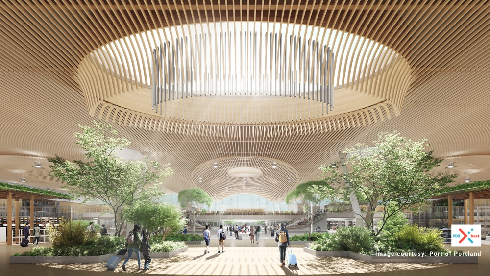
Portland International Airport (PDX) is getting a $2-billion makeover and the innovative, nine-acre, seismically isolated curved mass timber roof of the main terminal is at the epicenter of it all. The roof on the terminal core (TCORE) of PDX is part of a revamp to give it a warmer and people-friendly atmosphere. It consists of 277 80-ft glulam beams with 7.5 ft depth and a 16-ft arch. They are supported by large steel girders, between each of which, is an interface with the glulam at the bucket connections. The deck on top is made of 1347 2-inch thick locally sourced mass plywood panels (MPP) creating a diaphragm on the roof allowing for 10–ft on centre beam spacing. The roof is a giant sloping arch with large skylights and an undulating edge. There are more than 30,000 individual sticks of 3x6 lattice on the underside of the glulam beams. This project required a large team comprised of multiple companies/experts working together towards the same goal. Coordination and teamwork have been key to the success of the overall project. World class contractor - Swinerton and it's Mass Timber focused affiliate Timberlab, are handling the full timber fabrication & installation scope for this project with help from CadMakers (a Vancouver, Canada based VDC consultancy) providing digital fabrication twin services.
Mass timber uses state-of-the-art technology to glue, nail, or dowel wood products together in layers. The results are large structural panels, posts, and beams. BIM/VDC, which is traditional 3D computer modelling used for coordination, has been pushed to new levels on this project by involving general contractors, superintendents, project engineers and project managers to develop a fabrication level digital twin to assist the design, fabrication and installation process. The power of automation allows us to generate thousands and thousands of pieces with complex geometry within a strict project timeline.
In addition, to keep the airport in operation, the roof had to be split into 15 modules, pre-installed at a lay-down yard and reassembled at the terminal within a limited time window (airport shutdown hours). Therefore, extensive Design for Manufacture and Assembly (DFMA) considerations have been applied to the project and multiple dynamic installation processes have been simulated from the digital twin in advance.
CadMakers uses 3DExperience/CATIA, the same software being used by major aerospace and automotive companies, to create the fabrication package and installation guides for the project. One fun fact here is this might be the 1st time the aircrafts and the airport come from the same design platform in the manufacturing and construction world.
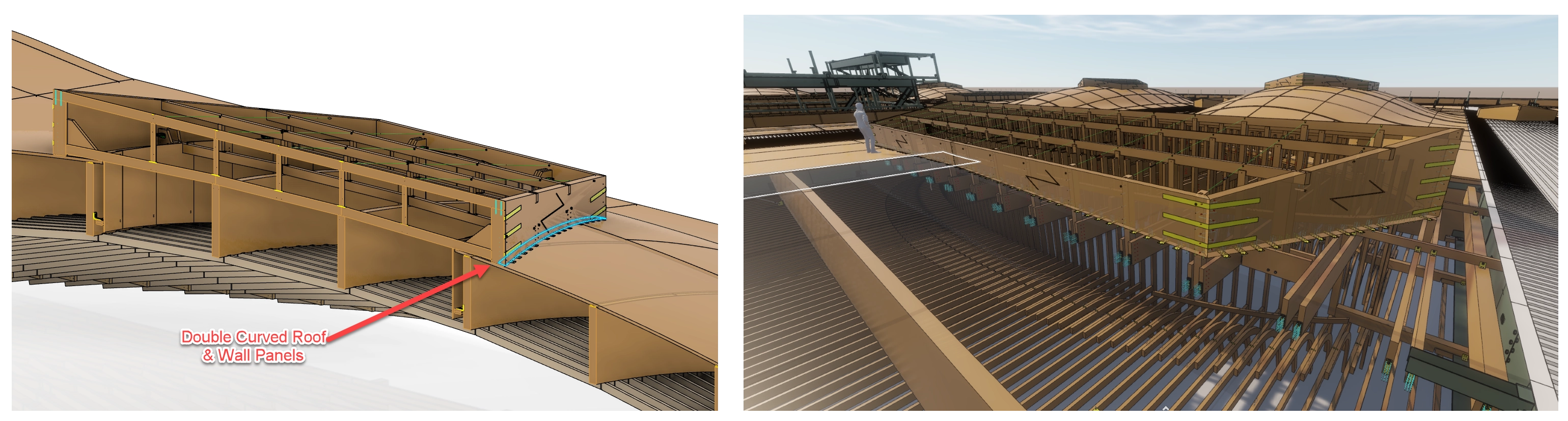
Curved Panels
The first challenge of the roof structure was to create a highly accurate master surface of the MPP panels following the 3 dimensional curvatures driven by the shape or the Glulam beams. Carl Guitard, project lead at CadMakers, who was previously a design & engineering supervisor from the automotive industry, managed this work with his brilliant surfacing skills.
.webp)
The second challenge of the roof MPP panels is that the MPP fabricator has to cut the panels flat, which means the curved roof panels had to be “flattened” into a developed shape during 3D modeling to be fabricated and then fitted (bent) to the roof curvature during on-site construction. Studies and information on the curving of MPP panels are extremely limited.
To solve this, we attempted different modeling methods to develop the roof panels into a flat shape. Considering the potential deviation between model and reality, we also coordinated with the installation team on optimization to eliminate extreme curves and to keep the material waste to a minimum.
The third challenge of the MPP roof panels was the complication due to data loss during the transfer of different file types. Many of the developed shapes of the roof panels contain edges with three dimensional curvatures. Some of the converted Computerized Numerical Control (CNC) files created difficulties for the machine to execute as well as long processing times.
Communication between all parties was key to identify these panels and further refine the model by either applying a slight change to the radius of the bend or smoothing/simplifying of the edge surfaces to facilitate the fabrication process.
Glulam Beams
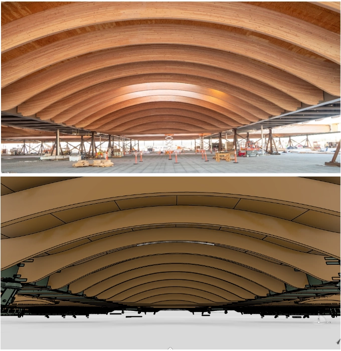
The glulam beams are connected to the steel frame structure which are directly supported by the main columns. These cambered beams are the main structural element that support the MPP roof panels, skylights and decorative lattice. The glulam beams have a span of 80 feet and a depth of 7.5 feet. Each beam is a continuous piece, meaning there is no splice, for aesthetic and structural reasons, which also reduces the cost of the steel hardware. In total, there are 837 glulam beams with 20+ different unique shapes (1684 elements).
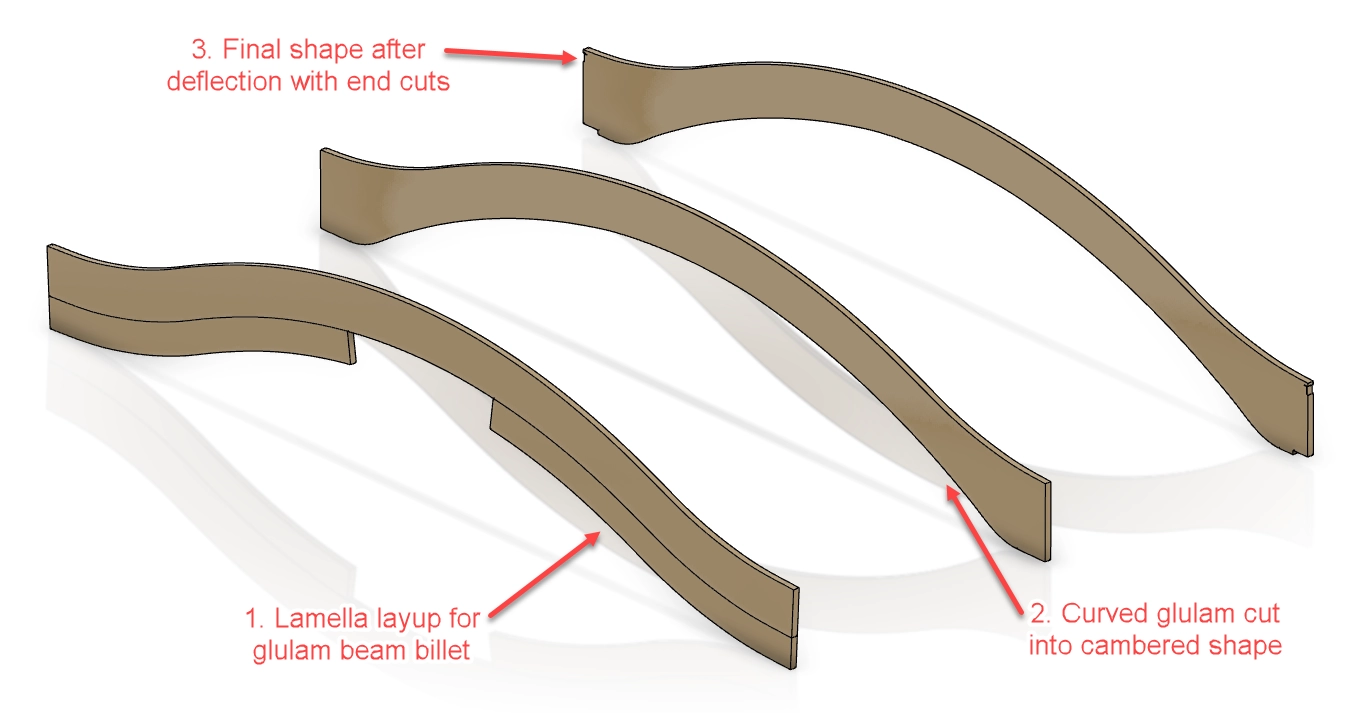
Due to the physical properties and long span of the glulam beams, as well as the weight of the roof structure, the arch of the beam will deform slightly after being installed. As a result, each type of beams has a camber for fabrication.
Both initial shape (for fabrication) and final installed shape (for coordination) were modelled. We considered the pre-cambered shape, especially at the end-cut for steel bucket connections to the frame structure. The beams were then accurately cut in the factory. These beams fit in the steel bucket end connection perfectly and deform to their final post-camber shapes, making the installation process efficient. With the success of glulam beam installation, the MPP roof panel followed smoothly.
For each beam there are four connections to the steel frame. Structural consultants designed a combination of 10 different details for the top connectors and 22 for the bottom connectors. We accurately produced the fabrication drawings according to the design and located each unique type in the floor plan assembly drawings.
Another key factor for the success of this project is the coordination with the steel manufacturer. The wood beams and panels are closely related to the position of the steel. We coordinated regularly with the steel trade for verification of all gap tolerances and potential clashes that are detectable only with a precise 3D model in such a variety of complicated situations. Coordinating with their steel 3D model allowed the team to foresee and identify constructability problems and coordinate the solutions before installation.
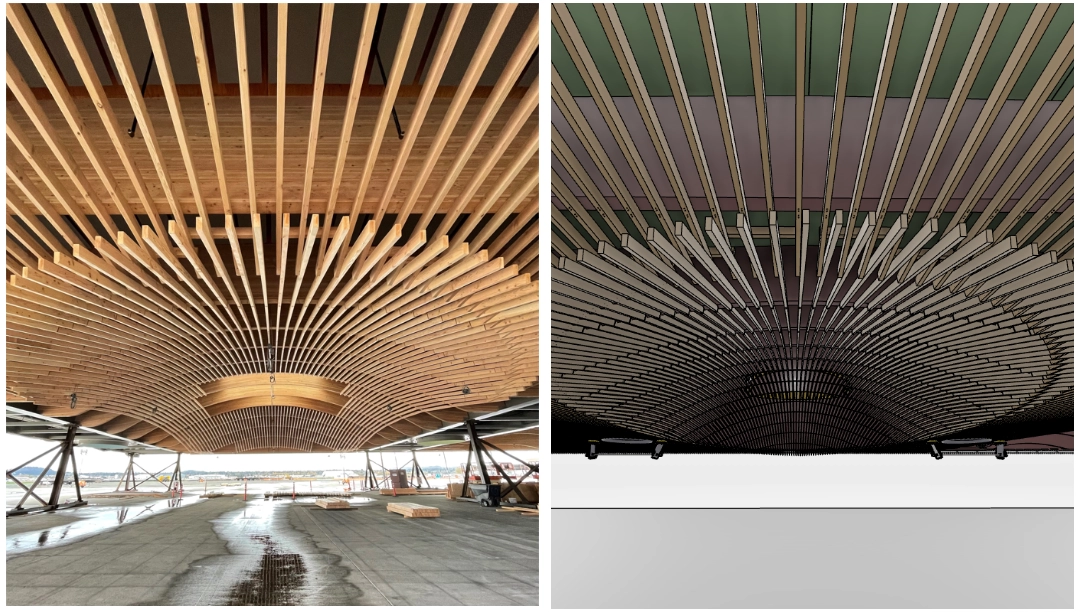
Lattice
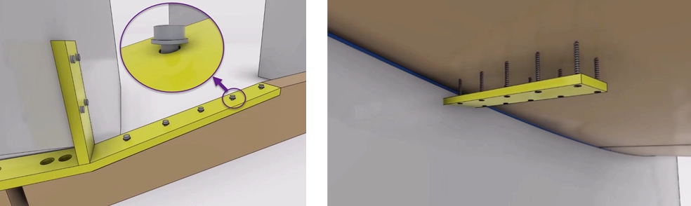
The nature of the lattice design following the dome shapes of the roof and its large quantities made it difficult for 2D design drawings to give the full picture. The challenge was finding all the unique conditions as they relate to each specific detail and then adapting to all the situations. To avoid any surprises and further comprehend the design intent, our strategy was to start from a virtual mock-up study with installation simulations. The process allowed the team to identify numerous situations that were not captured in the details. The findings ranged from the need to install screws at an angle with limited access for the tools (or use bevel washers) to the requirement of different angles of cross-bracing plates at each location to match the MPP roof curvature.
These simulations were of a significant value to the Superintendent at Swinerton and his team who were impressed with the results. The impressive fact here is that the initial study showing what possible situations might occur was done during the first two weeks after CadMakers joined the project.
Once the mock up process was complete, CadMakers automation team were able to integrate all the possible configurations and logics to our automation tools (30000+ lattices and countless unique situations). To save time and make deliverables ready ahead of deadlines, the team ran multiple computers in parallel to create critical geometry inputs (slope, start and end points), generate physical lattice, add fasteners/hardware and pre-drills and create the cross-bracing steel all simultaneously
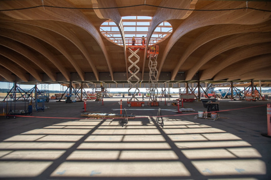
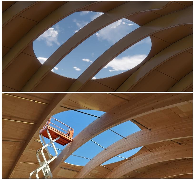
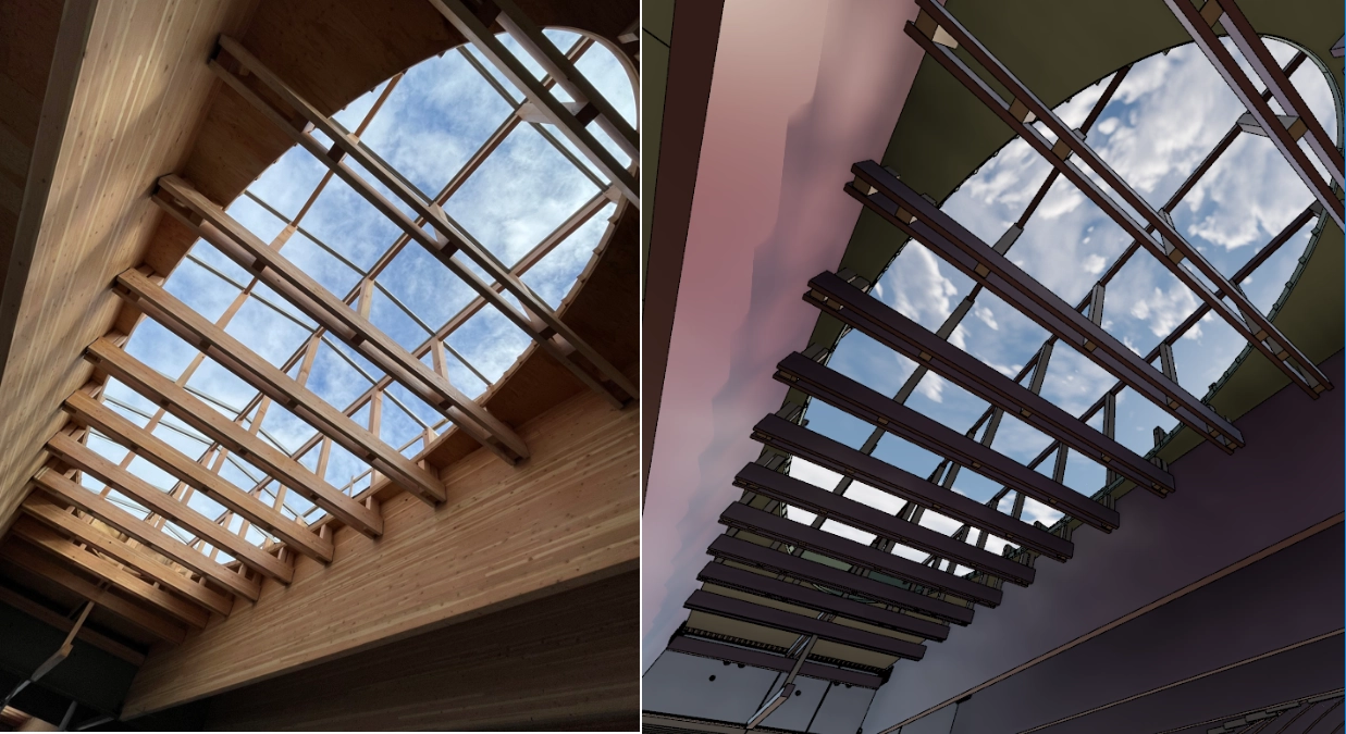
Skylights
There are six types of skylights made of thousands of individual elements. The last piece of the puzzle on this project; the skylights geometry depends on the complex shapes of other structural elements (steel, beams, MPP) of the roof.
To facilitate the challenges faced by the team on site to install the complex skylights, we created high level of details (LOD) drawing sets with QR codes that gave installers access to 3D models which included embedded installation animations through cmBuilder.io (our in-house site simulation platform).
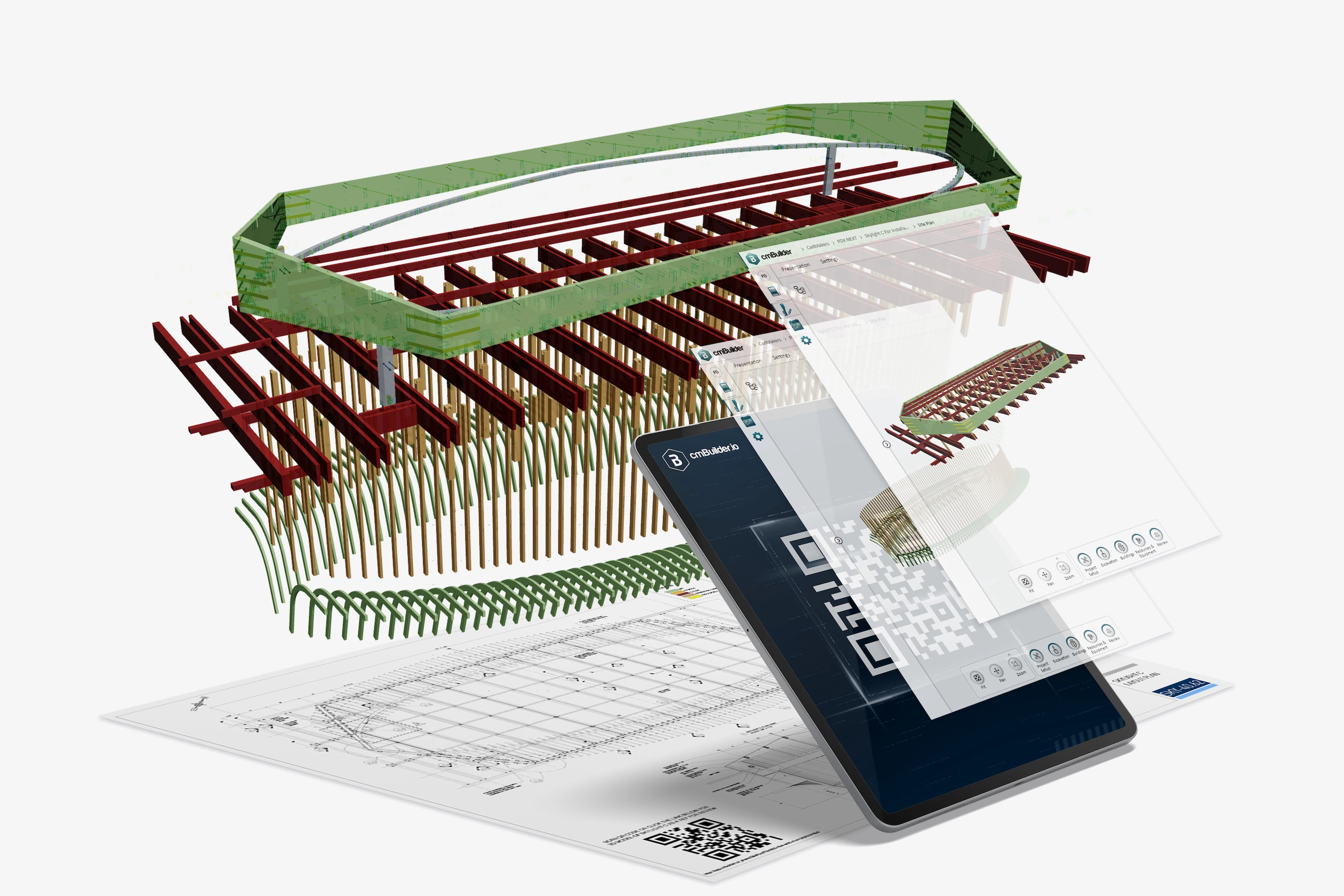
Installation of the MPP panels at the skylight resulted in a perfect circle without site adjustments. This was an indicator of the success of the entire process; modelling, fabricating and assembling with the precision of a high-detailed digital twin.
Off-Site Construction
This project is unique in its construction and assembly procedures. For multiple safety and operation reasons, the entire roof had to be constructed off-site in a lay-down yard and designed to be disassembled into very large modules (almost the size of a football field!). The modules are picked-up one at a time, carried to the terminal and re-assembled in their final place. The process is extremely complex, and time regulated as this happens on airport grounds. CadMakers provided insight into design changes and solutions required to clear the process of assembly/disassembly. The 3D simulations were key to determine with confidence that this movement between steel and timber structure (with tight tolerances) would happen smoothly, without clashes.
CadMakers’ team also worked out the naming convention/sequence and developed, with the customer, an efficient process for data management. Whether it was for manufacturers, fabricators or even computer programs – the information was easily recognizable by all.
Over the years, CadMakers has developed a good system for identifying and addressing issues. Providing rich information (with pictures attached and clear, concise questions) early in the process, allowed the Swinerton team to get quick answers and stay on schedule.

Project Details:
LOCATION - Portland, OR
OWNER - Port of Portland
CONTRACTOR - Hoffman Skanska Joint Venture
MASS TIMBER TRADE PARTNER: Swinerton
DETAILING AND FABRICATION PARTNER: Timberlab
ARCHITECT - ZGF Architects
STRUCTURAL ENGINEERS - KPFF